V • H • PThe Three Amigos of Antennas!Vertical • Horizontal • Power
There’s a New Sheriff in Town — a Friendly $5 Fuse |

|
If your locality has not regulated all three parameters — V • H • P — for wireless antennas, then it has accomplished nothing!
- Vertical Offset (in feet)
- Horizontal Offset (in feet)
- Maximum Effective Radiated Power (in Watts)
Let’s Do Some third-grade math:
- Length (in feet) × Width (in feet) = Area (in square feet)
- Speed (in miles per hour) × Time (in hours) = Distance (in miles)
- Maximum Input Power (in Watts) × Antenna-Gain (a unitless fraction, dBi) = Maximum Effective Radiated Power (in Watts ERP)
Now, let’s use some numbers . . .
- 30 feet × 50 feet = 1,500 square feet
- 30 miles per hour × 5 hours = 150 miles traveled
- 150 Watts × 10/1 dBi = 1,500 Watts ERP (Unbelievably, current plans for so-called “small” Wireless Telecommunications Facilities (sWTFs) call for 1,500 to 15,000 Watts of ERP as close as 6 to 12 feet from homes! — Read more here.)
- Even better 0.02 Watts × 5/1 dBi = 0.1 Watt ERP (Telecommunications Service requires only 0.1 Watt of ERP for five-bars on a cell phone in a ½-mile radius from the sWTF. Problem solved.)
What are the Wireless Cos. planning to do with all of that excess Effective Radiated Power (many tens of thousands of times too much)? . . . NOTHING GOOD . . . so even your local Planning Commissioners, City Council members or County Board of Supervisors can do third-grade math, can’t they?
1996 Telecommunications Act (1996-Act)
47 U.S. Code § 324 – Use of minimum power
In all circumstances, except in case of radio communications or signals relating to vessels in distress, all radio stations, including those owned and operated by the United States, shall use the minimum amount of power necessary to carry out the communication desired.
(June 19, 1934, ch. 652, title III, § 324, 48 Stat. 1091.)
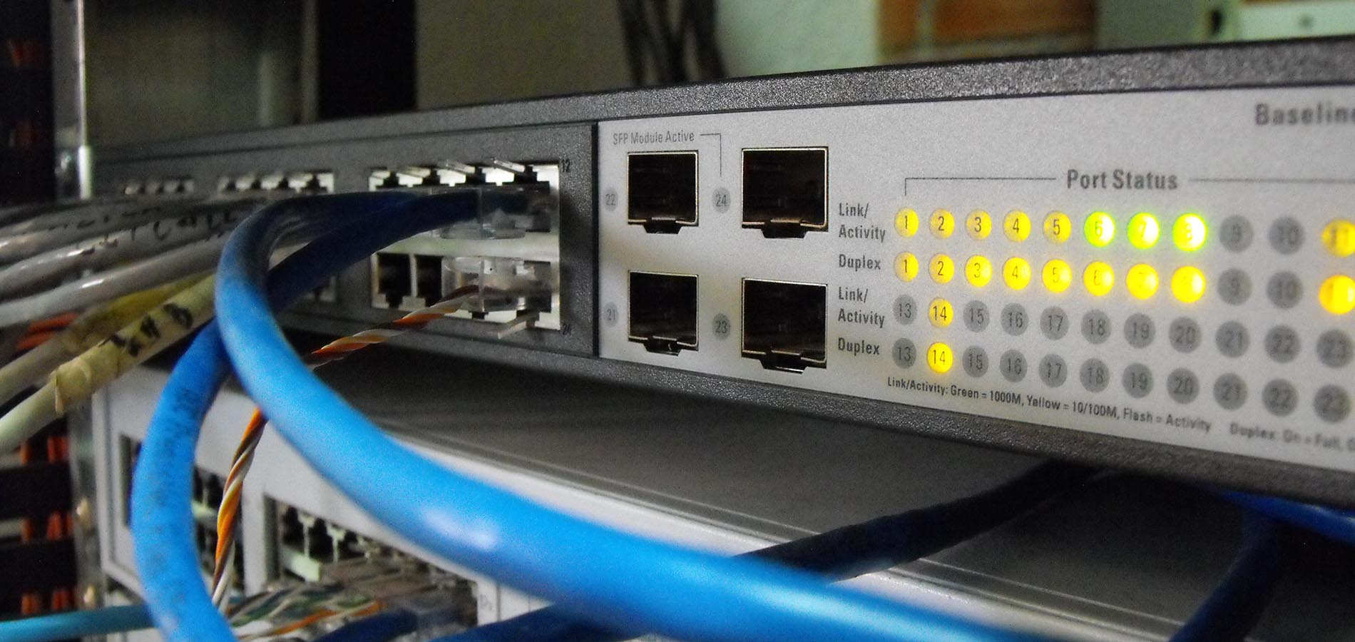
Cisco RF/MW Radiation Power Values — circa 2008
An improper combination of transmit power level and antenna gain can result in equivalent isotropic radiated power (EIRP) that exceeds the amount allowed per regulatory domain.
- For general information on power values, see RF Power Values (Document ID 23231)
- For general information on channel selection and transmit power, see the FCC Regulations Update For 2004 white paper
- Cisco has an Outdoor Bridge Range Calculation Utility to help determine what to expect from an outdoor wireless link.
V • H • P . . . for 2,400 MHz (2.4 GHz)
V • H • P = Vertical • Horizontal • Power
|
Wireless Link |
Approximate Value "F" |
Appoximate Value "C" |
Value "H" Antenna mounting Height |
|---|---|---|---|
| H = 1 mile | 14 | 3 | V = 17 feet |
| H = 5 miles | 31 | 5 | V = 36 feet* |
| H = 10 miles | 43 | 13 | V = 56 feet |
| H = 15 miles | 53 | 28 | V = 81 feet |
| H = 20 miles | 61 | 50 | V = 111 feet |
| H = 25 miles | 68 | 78 | V = 146 feet |
*For 2,400 MHz, what’s the Maximum Power Output in Effective Radiated Power (ERP)?

V • H • P . . . for 5,800 MHz (5.x GHz)
V • H • P = Vertical • Horizontal • Power
|
Wireless Link |
Approximate Value "F" |
Approximate Value "C" |
Value "H" Antenna mounting Height |
|---|---|---|---|
| H = 1 mile | 9 | 3 | V = 12 feet |
| H = 5 miles | 20 | 5 | V = 25 feet* |
| H = 10 miles | 28 | 13 | V = 41 feet |
| H = 15 miles | 35 | 28 | V = 63 feet |
| H = 20 miles | 40 | 50 | V = 90 feet |
| H = 25 miles | 45 | 78 | V = 123 feet |
*For 5,800 MHz, what’s the Maximum Power Output in Effective Radiated Power (ERP)?
To set the transmit power on the wireless device radio to one of the power levels allowed in your the United States, use the power local interface command.
Radio Transmit Power
For 802.11b 2.4 GHz radios, the settings are in mW:
- Power output options: [1 | 5 | 20 | 30 | 50 | 100 mW is the maximum]
For 802.11g, 2.4 GHz radios. the settings are in mW:
- Power output options: {cck | ofdm} [1 | 5 | 20 | 30 | 50 | 100 mW is the maximum]
For 802.11g, 2.4 GHz radios where the settings are in dBm:
- Power output options: {cck | ofdm} [1 | 2 | 5 | 8 | 11 | 14 | 16 | 17 | 20 dBm is the maximum]
For 802.11a, 5 GHz radios radios where the settings are in mW:
- Power output options: {cck | ofdm} [5 | 10 | 20 | 40 mW is the maximum]
For 802.11a, 5 GHz radio where the settings are in dBm:
- Power output options: {cck | ofdm} [1 | 2 | 5 | 8 | 11 | 14 | 16 | 17 dBm is the maximum]
Legend:
- cck = Complementary Code Keying, which is supported by 802.11b and 802.11g devices.
- ofdm = Orthogonal Frequency Division Multiplexing, which is supported by 802.11g and 802.11a devices
mW to dBm Power Conversion Table
|
mW |
dBm |
|---|---|
| 1 | 0 |
| 2 | 2 |
| 3 | 5 |
| 4 | 6 |
| 5 | 7 |
| 6 | 8 |
| 8 | 9 |
| 10 | 10 |
| 12 | 11 |
| 15 | 12 |
| 20 | 13 |
| 25 | 14 |
| 30 | 15 |
| 40 | 16 |
| 50 | 17 |
| 60 | 18 |
| 80 | 19 |
| 100 | 20 |
Antenna Gains Allowed for Different Modulation Schemes
|
Antenna Gain |
CCK Max Power |
OFDM Max Power |
|---|---|---|
| 2.2 | 100 | 30 |
| 6 | 100 | 30 |
| 6.5 | 100 | 30 |
| 10 | 100 | 30 |
| 13.5 | 100 | 30 |
| 15 | 50 | 20 |
| 21 | 20 | 10 |
Introduction
This document defines radio frequency (RF) power levels and the most common measure, the decibel (dB). This information can be very useful when you troubleshoot intermittent connectivity.
Power Level
The dB measures the power of a signal as a function of its ratio to another standardized value. The abbreviation dB is often combined with other abbreviations in order to represent the values that are compared.
In deciBel milliWatts (dBm), zero is arbitrarily set to 1 mW (1/1000th of a Watt).
You can calculate the power in dBs from this formula:
Power (in dB) = 10 * log10 (Signal/Reference)
This list defines the terms in the formula:
log10is logarithm base 10.Signalis the power of the signal (for example, 50 mW).Referenceis the reference power (for example, 1 mW).
Here is an example. If you want to calculate the power in dB of 50 mW, apply the formula in order to get:
Power (in dB) = 10 * log10 (50/1) = 10 * log10 (50) = 10 * 1.7 = 17 dBm
Because decibels are ratios that compare two power levels, you can use simple math in order to manipulate the ratios for the design and assembly of networks. For example, you can apply this basic rule in order to calculate logarithms of large numbers:
log10 (A*B) = log10(A) + log10(B)
If you use the formula above, you can calculate the power of 50 mW in dBs in this way:
Power (in dB) = 10 * log10 (50) = 10 * log10 (5 * 10) = (10 * log10 (5)) + (10 * log10(10)) = 7 + 10 = 17 dBm
These are commonly used general rules:
|
dB |
Transmit Power |
|---|---|
| 3 dB | 2x the transmit power |
| -3 dB | ½ the transmit power |
| 6 dB | 4x the transmit power |
| -6 dB | ¼ the transmit power |
| 10 dB | 10x the transmit power |
| -10 dB | 1/10th of transmit power |
| 20 dB | 100x the transmit power |
| -20 dB | 1/100th of transmit power |
| 30 dB | 1,000x the transmit power |
| -30 dB | 1/1,000th of transmit power |
Approximate dBm to mW Conversion
|
dBm |
mW |
|---|---|
| 0 | 1 |
| 1 | 1.25 |
| 2 | 1.56 |
| 3 | 2 |
| 4 | 2.5 |
| 5 | 3.12 |
| 6 | 4 |
| 7 | 5 |
| 8 | 6.25 |
| 9 | 8 |
| 10 | 10 |
| 11 | 12.5 |
| 12 | 16 |
| 13 | 20 |
| 14 | 25 |
| 15 | 32 |
| 16 | 40 |
| 17 | 50 |
| 18 | 64 |
| 19 | 80 |
| 20 | 100 |
| 21 | 128 |
| 22 | 160 |
| 23 | 200 |
| 24 | 256 |
| 25 | 320 |
| 26 | 400 |
| 27 | 512 |
| 28 | 640 |
| 29 | 800 |
| 30 | 1000 or 1 W |
Please follow this example:
- If 0 dB = 1 mW, then 10 dB = 10 mW, and 20 dB = 100 mW.
- Subtract 3 dB from 100 mW in order to drop the power by half (17 dB = 50 mW).
- Then, subtract 3 dB again in order to drop the power by 50 percent again (14 dB = 25 mW).
Antennas
You can also use the dB abbreviation in order to describe the power level rating of antennas:
- dBi— For use with isotropic antennas. Isotropic antennas are theoretical antennas that transmit equal power density in all directions. They are used only as theoretical (mathematical) references. They do not exist in the real world.
- dBd—With reference to dipole antennas.
- Isotropic antenna power is the ideal measurement to which antennas are compared. All FCC calculations use this measurement (dBi).
- Dipole antennas are more real-world antennas. While some antennas are rated in dBd, the majority of antennas are rated at dBi.
- The power rating difference between dBd and dBi is approximately 2.2—that is, 0 dBd = 2.2 dBi. Therefore, an antenna that is rated at 3 dBd is rated by the FCC (and Cisco) as 5.2 dBi.
Effective Isotropic Radiated Power
The radiated (transmitted) power is rated in either dBm or W. Power that comes off an antenna is measured as effective isotropic radiated power (EIRP). EIRP is the value the FCC uses to determine and measure power limits in applications such as 2.4-GHz or 5-GHz wireless equipment. In order to calculate EIRP, add
- take the transmitter power (in dBm)
- add the antenna gain (in dBi)
- subtract any cable losses (in dB).
| Cisco Parts | Cisco Part Number | Power |
|---|---|---|
| A Cisco Aironet Bridge | AIR-BR350-A-K9 | 20 dBm |
| That uses a 50 foot antenna cable | AIR-CAB050LL-R | (3.35 dB loss) |
| And a solid dish antenna | AIR-ANT3338 | 21 dBi gain |
| Has an EIRP of | 37.65 dBm |
Path Loss
The distance that a signal can be transmitted depends on several factors. The primary hardware factors that are involved are:
- Transmitter power
- Cable losses between the transmitter and its antenna
- Antenna gain of the transmitter
- How far apart the antennas are and if there are obstacles between them.
- Antennas that can see each other without any obstacles between them are in line of sight.
- Receiving antenna gain
- Cable losses between the receiver and its antenna
- Receiver sensitivity
Receiver sensitivity is defined as the minimum signal power level (in dBm or mW) that is necessary for the receiver to accurately decode a given signal. Because dBm is compared to 0 mW, 0 dBm is a relative point, much like 0 degrees is in temperature measurement. This table shows example values of receiver sensitivity:
Receiver Sensitivity: deciBel-milliWatt (dBm) to milliWatt (mW)
|
dBm |
mW |
|---|---|
| 10 | 10 |
| 3 | 2 |
| 0 | 1 |
| -3 | 0.5 |
| -10 | 0.1 |
| -20 | 0.01 |
| -30 | 0.001 |
| -40 | 0.0001 |
| -50 | 0.00001 |
| -60 | 0.000001 |
| -70 | 0.0000001 |
| -80 | 0.00000001 |
| -90 | 0.000000001 |
The receiver sensitivity of the radios in Aironet products is -84 dBm or 0.000000004 mW.
Estimate Outdoor Ranges
Cisco has an Outdoor Bridge Range Calculation Utility to help determine what to expect from an outdoor wireless link. Because the outputs of the calculation utility are theoretical, it is helpful to have some guidelines on how to help counteract outside factors.
- For every increase of 6 dB, the coverage distance doubles.
- For every decrease of 6 dB, the coverage distance is cut in half.
In order to make these adjustments, choose antennas with higher (or lower) gain. Or use longer (or shorter) antenna cables.
Given that a pair of Aironet 350 Bridges (with 50 feet of cable that connects to a dish antenna) can span 18 miles, you can modify the theoretical performance of that installation:
- If you change to 100-foot cables instead of 50-foot (which adds 3 dB of loss on each end), the range drops to 9 miles.
- If you change the antenna to 13.5-dBi yagis instead of the dishes (which reduces gain by 14 dBi overall), the range drops to less than 4 miles.
Estimate Indoor Ranges
There is no antenna calculation utility for indoor links. Indoor RF propagation is different than outdoor propagation. However, there are some quick calculations that you can do in order to estimate performance.
- For every increase of 9 dB, the coverage area doubles.
- For every decrease of 9 dB, the coverage area is cut in half.
Consider the typical installation of an Aironet 340 Access Point (AP) with the rubber ducky 2.2-dBi dipole antenna. The radio is approximately 15 dBm.
If you upgrade to a 350 AP and replace the rubber duckies with a high-gain omni-directional antenna that is rated at 5.2 dBi, the range nearly doubles.
The increase in power from a 340 AP to a 350 AP is +5 dBi. And the antenna upgrade is +3 dBi, for a total of +8 dBi.
This is close to the +9 dBi that are required to double the coverage area.
Related Information
- Cisco Aironet Antenna Reference Guide
- Outdoor Bridge Range Calculation Utility
- Intermittent Connectivity Issues in Wireless Bridges
- Troubleshooting Connectivity in a Wireless LAN Network
- Wireless LAN Technology Support
- Technical Support & Documentation – Cisco Systems
Localities Can Police the Quiet Enjoyment of Streets
Unfettered Effective Radiated Power results in too much ELECTROMAGNETIC NOISE on our streets.
In order to preserve the QUIET ENJOYMENT OF STREETS (QES), a locality can pass an ORDINANCE that limits the EFFECTIVE RADIATED POWER (ERP) of Wireless Telecommunications Facilities (WTFs), using simple language, like the following:
"For any Close Proximity Microwave Radiation Antennas (CPMRA) Wireless Telecommunications Facility (WTF) that is
- installed in the public rights-of-way, or
- attached to any building, or
- has antennas installed at a height that is lower than 100 feet off the ground,
. . . the applicant must install only antennas, radios and other supporting equipment that have no chance of exceeding a total of 0.1 Watt of effective radiated power from the face of the antenna shroud."

A cap of 0.1 Watt of ERP for each qualifying CPMRA provides four main benefits:
-
Provides coverage for Telecommunications service for about 1/2 mile from the source antenna (more than double the distance of the industry-claimed need of 1,000 feet down the block)
-
Does not effectively prohibit Telecommunications service, making this regulation legally defensible to Wireless industry challenge
-
Adds the "speed limits, seat belts and airbags" that residents need to be protect the quiet enjoyment of streets (part of the any city’s police powers over aesthetics). Read more here and here.
-
Complies with all FCC RF-EMR exposure guidelines.
You May As Well Forget About the AAA’s: the Altitude and Azimuth, which are the Angles of Propagation — as they are unnecessarily complicated . . .
For those who care, Altitude (up-and-down) and Azimuth (side-to-side) Describe How Wireless Signals Spray

The altitude is the angle up or down from the horizon — a typical 48″ tall small Wireless Telecommunications Facility (sWTF) antenna sprays wireless signal about 15° up and sprays wireless signal about 15° down from a horizontal plane located at the mid-point of the vertically-oriented antenna.
The azimuth is the angle formed between a reference direction (in this example north) and a line from the observer to a point of interest projected on the same plane as the reference direction orthogonal to the zenith.
What Do You Mean Unnecessarily Complicated?
Well, there is theory, practice and what really matters (Effective Radiated Power). Antenna theory often starts with an isoptropic antenna: an antenna that propagates in spherical shape from a point source. This is fine for learning, but you will find very few actual isotropic antennas in the field. WTF Antennas, in practice, are often a collection of vertically-oriented antennas, hidden behind an antenna shroud that is typically made of fiberglass to allow wireless signals to flow freely. Now the fact that the antenna elements are hidden from view allows the Wireless industry to bamboozle everyone at every step along the way and allows them to never give you a straight answer because every answer starts with “it depends” . . . on the vertical height at which the antennas are installed, on the horizontal distance from the antennas, on the power output that constantly varies, on the reflection of signals, on the absorption of signals, on the interference between signals, on the topography, on the trees and buildings nearby, on the numbers of simultaneous users and on and on and on . . .
The good news is that for smart, effective, bullet-proof local Municipal Wireless Code, a City or County doesn’t have to worry about anything other than Effective Radiated Power, which according to Site Safe, LLC is calculated using third-grade math (A × B = C):
Maximum Input Power (in Watts) × Antenna-Gain (a unitless fraction) = Maximum Effective Radiated Power (in Watts ERP)
Effective Radiated Power (ERP) — the product of the power supplied to the antenna and the antenna gain in a given direction relative to a half-wave dipole antenna.
Antenna Gain — the ratio, usually expressed in decibels, of the power required at the input of a loss-free reference antenna to the power supplied to the input of the given antenna to produce, in a given direction, the same field strength or the same power density at the same distance. When not specified otherwise, the gain refers to the direction of maximum radiation. Gain may be considered for a specified polarization. Gain may be referenced to an isotropic antenna (dBi) or a half-wave dipole (dBd) antenna.
An Effective Radiated Power Limit of 0.1 Watts for all antennas within — and for all frequencies transmitted from — a CPRMA-WTF Antenna Shroud Can be Enforced 24/7 by a $5.00 Fuse that is under a locality’s lock-and-key and placed on every CPMRA-WTF installation

Localities can use their local police powers over the public rights-of-way to preserve the quiet enjoyment of streets by requiring two additional boxes on every CPMRA-WTF installation:
- A Fuse Box: this gives control — and revenue (via policing fees) back to the locality (City or County)
- A Fiber Optic Sharing Box: this ensures public benefit from fiber optic installations in the public rights-of-way. Sending Big Data (for video/music streaming, gaming or Internet) directly to homes via Wireline Fiber Optic cables and copper uses much less energy than via Wireless. Private wireless Cos. should not be allowed to hoard the use of fiber optic cables in the public rights-of-way for their sole benefit. The fiber optic cables, instead can be shared with the residents, as a condition for gaining access to the public rights-of-way. This is a fair rule that can apply to all Wireless providers in a non-discriminatory way.
Localities can also levy fines for ERP violations and set up a three-strikes-and-you’re-out program as a revenue-generating way to police Big Wireless which is attempting to take away local Cities’ control over the public rights-of-way. That attempt is illegal and inconsistent with the legislative intent of the 1996 Telecommunications Act. Read further here and here.
All of this Local Benefit Just From Regulating Effective Radiated Power? Where Do I Learn More? . . . Look No Further Than Wi-Fi!
Lessons From Wi-Fi . . . See that Nighthawk Wireless Router in the Photo? Wireless Equipment That Size is All That is Needed for CPMRA-WTF Installations on Utility/Light Poles: 4-inch — Not 4-Foot — Antennas
Learn more about Wireless Routers — here and here.

FCC §15.223 Operation in the band 1.705-10 MHz.
(a) The field strength of any emission within the band 1.705-10.0 MHz shall not exceed 100 microvolts/meter (0.00003 µW/m²) at a distance of 30 meters (98.5 feet).
From a Class B Approval —> FCC ID: LZKM900D1
- Application: Data Transceiver Maximum output power: 100 mW (0.1 Watt)
- Equipment Class: DSS – Part 15 Spread Spectrum Transmitter
§15.247 Operation within the following Wi-Fi Frequency bands
• 902-928 MHz,
• 2400-2483.5 MHz, and
• 5725-5850 MHz.
(a) Operation under the provisions of this Section is limited to
- frequency hopping intentional radiators
- digitally modulated intentional radiators
. . . that comply with the following provisions:
From Wikipedia:
Frequency-hopping spread spectrum (FHSS) is a method of transmitting radio signals by rapidly changing the carrier frequency among many distinct frequencies occupying a large spectral band. The changes are controlled by a code known to both transmitter and receiver. FHSS is used to avoid interference, to prevent eavesdropping, and to enable code-division multiple access (CDMA) communications
In the US, since the Federal Communications Commission (FCC) amended rules to allow FHSS systems in the unregulated 2.4 GHz band, many consumer devices in that band have employed various FHSS modes.
eFCC CFR 47 part 15.247 covers the regulations in the US for 902-928 MHz, 2400-2483.5 MHz, and 5725-5850 MHz bands, and the requirements for frequency hopping
Some walkie-talkies that employ FHSS technology have been developed for unlicensed use on the 900 MHz band.
FHSS technology is also used in many hobby radio-controlled transmitters and receivers used for model cars, airplanes, and drones.
The transmitter will use all the channels in a fixed period of time. The receiver can then find the transmitter by picking a random channel and listening for valid data on that channel. The transmitter’s data is identified by a special sequence of data that is unlikely to occur over the segment of data for this channel.
In the US, FCC part 15 on unlicensed spread spectrum systems in the 902–928 MHz and 2.4 GHz bands permits more power than is allowed for non-spread-spectrum systems. Both FHSS and direct-sequence spread-spectrum (DSSS) systems can transmit at 1 Watt. The Federal Communications Commission (FCC) also prescribes a minimum number of frequency channelsand a maximum dwell time for each channel:
| Frequencies | Channels | Dwell Time | Max Total Transmit Power |
| 902–928 MHz | 50 or more | 0.4 sec. in 10-20 sec. period | 1 Watt for 50+ channels; 0.25 Watt for 25-49 channels |
| 2400-2483.5 MHz | 15 or more | 0.4 sec. in 0.4 sec. period × number of hopping channels used | 1 Watt for 75+ channels; 0.125 Watt for <75 channels |
| 5725-5850 MHz | 75 or more | 0.4 sec. in 30 sec. period | 1 Watt for 75+ channels |
Based on the use of antennas with directional gains that do not exceed 6 dBi
A glance at today’s Router Ranker shows products using four MIMO streams dominating the top ranker positions. This isn’t because they have more power, because all products must obey transmit power limits, which include effective gains due to antenna design and even beamforming.
-
The reason for the higher ranking of four stream products is the increased transmit spatial multiplexing gain and receive diversity gain provided by using more MIMO streams. A four-stream product wireless router provides higher throughput at lower signal levels because it improves effective range, i.e. the area where you get throughput you can actually use.
-
Cramming too many nodes in too small a space may result in degraded performance due to co-channel interference. More is not always better in the world of Wi-Fi.
- What is the key learning? Since it is illegal to mount this Nighthawk Wi-Fi router outside (because it would cause interference), then it logically follows that 100 milliWatts (0.1 Watt) of Effective Radiated Power is more than sufficient — in fact, sufficient to provide telecommunications service in a ½-mile radius.

Lessons From FCC Rules

FCC Office of Engineering & Technology Bulletin No. 62
Digital devices fall into two categories — Class A and Class B
- Class A digital devices are ones that are marketed exclusively for use in business, industrial and commercial environments.
- Class B digital devices are ones that are marketed for use anywhere, including residential environments.
The technical standards for Class B equipment are stricter than those for Class A equipment because the Class B equipment may be located closer to radios, TVs, and other receivers that tend to be susceptible to interference. The Class B technical standards are designed to protect against interference being caused to a receiver located about 10 meters away.
Q: What is the difference between a Class A and Class B digital device? If a digital device will be sold to anyone who is likely to use it in a residential environment then it is a Class B digital device. When determining whether a particular device should be classified as Class A or Class B, the Commission normally considers the following three questions, in this order:
The FCC rules are contained in Title 47 of the Code of Federal Regulations (47 CFR), Part 2 and Part 15 are applicable to computers and other digital devices. Digital devices that connect to the public switched telephone network are subject to Part 68 registration requirements.


§15.15 General technical requirements.
(a) An intentional or unintentional radiator shall be constructed in accordance with good engineering design and manufacturing practice. Emanations from the device shall be suppressed as much as practicable, but in no case shall the emanations exceed the levels specified in these rules.
(b) Except as follows, an intentional or unintentional radiator must be constructed such that the adjustments of any control that is readily accessible by or intended to be accessible to the user will not cause operation of the device in violation of the regulations. Access BPL equipment shall comply with the applicable standards at the control adjustment that is employed. The measurement report used in support of an application for Certification and the user instructions for Access BPL equipment shall clearly specify the user-or installer-control settings that are required for conformance with these regulations.
(c) Parties responsible for equipment compliance should note that the limits specified in this part will not prevent harmful interference under all circumstances. Since the operators of part 15 devices are required to cease operation should harmful interference occur to authorized users of the radio frequency spectrum, the parties responsible for equipment compliance are encouraged to employ the minimum field strength necessary for communications, to provide greater attenuation of unwanted emissions than required by these regulations, and to advise the user as to how to resolve harmful interference problems (for example, see §15.105(b))
§15.209 Radiated emission limits; general requirements.
(a) Except as provided elsewhere in this subpart, the emissions from an intentional radiator shall not exceed the field strength levels specified in the following table:
Using the PowerWatch Calculator here:
|
|
(e) The provisions in §15.31, §15.33, and §15.35 for measuring emissions at distances other than the distances specified in the above table, determining the frequency range over which radiated emissions are to be measured, and limiting peak emissions apply to all devices operated under this part
§15.33 Frequency range of radiated measurements.
(a) For an intentional radiator, the spectrum shall be investigated from the lowest radio frequency signal generated in the device, without going below 9 kHz, up to at least the frequency shown in this paragraph:
(1) If the intentional radiator operates below 10 GHz: to the tenth harmonic of the highest fundamental frequency or to 40 GHz, whichever is lower.
(2) If the intentional radiator operates at or above 10 GHz and below 30 GHz: to the fifth harmonic of the highest fundamental frequency or to 100 GHz, whichever is lower.
(3) If the intentional radiator operates at or above 30 GHz: to the fifth harmonic of the highest fundamental frequency or to 200 GHz, whichever is lower, unless specified otherwise elsewhere in the rules.
(4) If the intentional radiator operates at or above 95 GHz: To the third harmonic of the highest fundamental frequency or to 750 GHz, whichever is lower, unless specified otherwise elsewhere in the rules.
(5) If the intentional radiator contains a digital device, regardless of whether this digital device controls the functions of the intentional radiator or the digital device is used for additional control or function purposes other than to enable the operation of the intentional radiator, the frequency range shall be investigated up to the range specified in paragraphs (a)(1) through (4) of this section or the range applicable to the digital device, as shown in paragraph (b)(1) of this section, whichever is the higher frequency range of investigation.
§15.35 Measurement detector functions and bandwidths.
The conducted and radiated emission limits shown in this part are based on the following, unless otherwise specified in this part:
(a) On any frequency or frequencies below or equal to 1000 MHz, the limits shown are based on measuring equipment employing a CISPR quasi-peak detector function and related measurement bandwidths, unless otherwise specified. The specifications for the measuring instrumentation using the CISPR quasi-peak detector can be found in ANSI C63.4-2014, clause 4 (incorporated by reference, see §15.38). As an alternative to CISPR quasi-peak measurements, the responsible party, at its option, may demonstrate compliance with the emission limits using measuring equipment employing a peak detector function as long at the same bandwidth as indicated for CISPR quasi-peak measurements are employed.
(b) Unless otherwise specified, on any frequency or frequencies above 1000 MHz, the radiated emission limits are based on the use of measurement instrumentation employing an average detector function. Unless otherwise specified, measurements above 1000 MHz shall be performed using a minimum resolution bandwidth of 1 MHz. When average radiated emission measurements are specified in this part, including average emission measurements below 1000 MHz, there also is a limit on the peak level of the radio frequency emissions. Unless otherwise specified, e.g., see §§15.250, 15.252, 15.253(d), 15.255, 15.256, and 15.509 through 15.519, the limit on peak radio frequency emissions is 20 dB above the maximum permitted average emission limit applicable to the equipment under test. This peak limit applies to the total peak emission level radiated by the device, e.g., the total peak power level. Note that the use of a pulse desensitization correction factor may be needed to determine the total peak emission level. The instruction manual or application note for the measurement instrument should be consulted for determining pulse desensitization factors, as necessary.
(c) Unless otherwise specified, e.g., §§15.255(b), and 15.256(l)(5), when the radiated emission limits are expressed in terms of the average value of the emission, and pulsed operation is employed, the measurement field strength shall be determined by averaging over one complete pulse train, including blanking intervals, as long as the pulse train does not exceed 0.1 seconds. As an alternative (provided the transmitter operates for longer than 0.1 seconds) or in cases where the pulse train exceeds 0.1 seconds, the measured field strength shall be determined from the average absolute voltage during a 0.1 second interval during which the field strength is at its maximum value. The exact method of calculating the average field strength shall be submitted with any application for certification or shall be retained in the measurement data file for equipment subject to Supplier’s Declaration of Conformity.
You must be logged in to post a comment.